 |
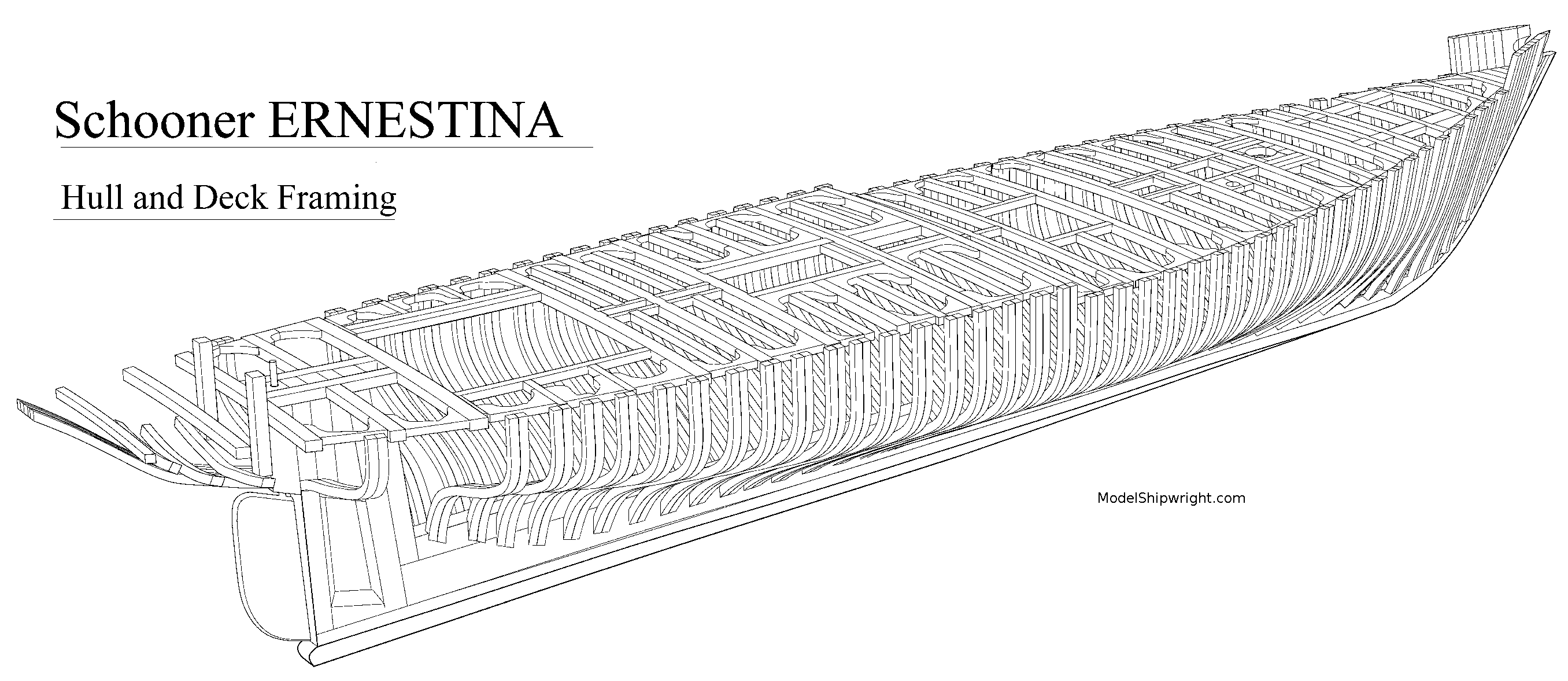
| Figure 1. Perspective view of Grand Banks fishing schooner Ernestina courtesy Library of Congress |
Now that you've learned how to “read” a ship plan, let's talk about the components that create the three-dimensional shape of a ship's hull that is represented in two dimensions on those plans.
The shape of a ship's hull is determined by five main structural members: The keel, the frames (sometimes referred to as ribs), the stem and stern posts, and the deck beams. A perspective view of these main structural members can be seen in figure 1, the hull framing of the 1894 Glouster-built Grand Banks fishing schooner Effie M. Morrissey, later renamed Ernestina. The remaining illustrations will all reference the 1893 Essex, Massachusetts-built inshore fishing schooner Lettie G. Howard, figure 2. While she is smaller than the Ernestina, she is built to a similar style.
 |
| Figure 2. Plans of schooner Lettie G. Howard courtesy Library of Congress |
The Keel
Charles Davis defines the keel asConstruction of a ship's hull begins with the laying of the keel, which forms the backbone of the ship. The frames, stem and stern posts are all fitted to the keel.“the fore-and-aft construction of heavy timbers scarfed end to end and extending
through from the stem-post to the stern; and rudder-post, on the outside of the bottom of a vessel along the center line.”
The Frames
The frames are transverse ribs set (mostly - more on this later) at 90-degree angle to the keel. The frames are shaped to a curve determined by the table of offsets on the ship plan, and shown visually on the body plan. The frames determine the “fullness” of the hull.The Stem Post
Davis defines the stem as“a heavy timber forming the extreme bow of the ship extending from the keel to the forecastle deck.”The forward end of a ship's planking terminates at the “rabbet,” an angled groove cut into the stem and the ends of plank strakes are firmly fastened in place on the stem.
The Stern Post
The stern post is a heavy timber secured at its lower end to the after end of a keel, the upper end supporting the transom and the horn timbers. It supports a number of structural members that make the ship very strong and rigid at this part of the hull. The aft end of lower hull planking terminates at the rabbet in the stern-post, and plank strakes are securely fastened to it. |
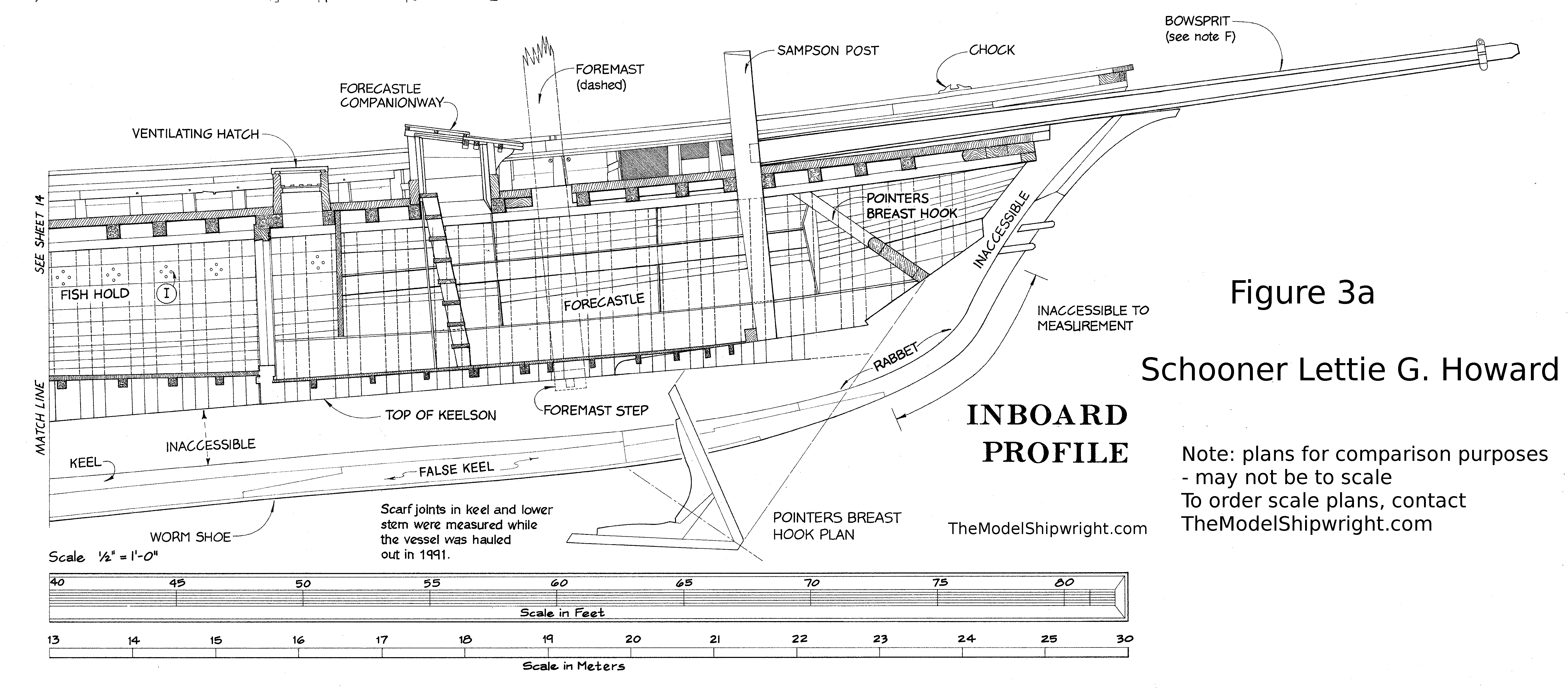
| Figure 3a. Inboard profile, bow, Lettie G. Howard |
The Deck Beams
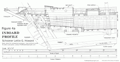
The deck beams are “athwartship” timbers, that is, they run at 90 degree angles to the keel. They are the horizontal equivalent of the vertical frames. Deck planking is laid fore-and-aft across the deck beams, which are usually crowned in the middle in an arc of a circle to assist the flow of water off the deck in bad weather.Figures 3a and 4a show the bow and stern inboard profile (side view, from the centerline out, showing internal structural members) of the Lettie G. Howard. These plans were drafted long after the ship was built, so there are areas hidden from view. These are marked “inaccessible” on the plan, but we have included figures 3b and 4b which are drawings from Charles Davis' “The Building of a Wooden Ship” to show details similar to that which is hidden on the Howard plans.
 |
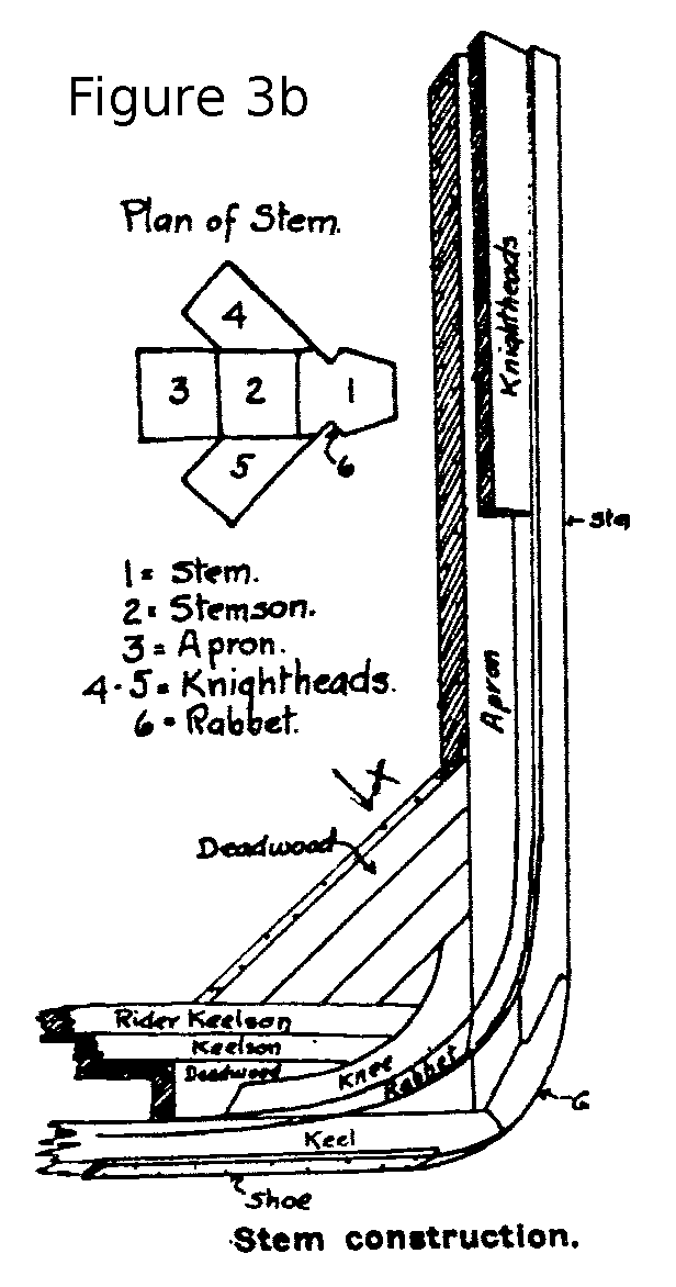
| Figure 3b. Bow structure |
The most important detail to note in figure 3b is where the keel and stem come together. One error in the Davis drawing is number 6, which should read “Gripe” instead of Rabbet. The gripe is a corner-piece, generally made from a natural timber crook, which joins the stem and the front end of the keel at the forefoot. Not all ships have a gripe, in some the stem post is scarphed right onto the keel. Also note in figure 3b the various parts that make up the stem: The Stem, Stemson, Apron, Knightheads, and Gripe. There is another corner-piece, or knee, on the inside of the joint between the keel and stem to add strength to that area. All of this detail was inaccessible to the surveyor that drew the plans in 1989. Figure 3b also shows the layers of keelson timbers joining to the stem, and “deadwood” filling the space between the two structural members. The deadwood provides a place to secure the bottoms of the “cant” frames at the bow, which, unlike the “square frames,” do not cross the keel. They are half-frames set at an angle (canted) to provide a better surface for attaching planking strakes.
 |
| Figure 4a. Inboard profile Lettie G. Howard courtesy Library of Congress |
 |
| Figure 4b. Stern Construction |
 |
| Figure 5. Deck Framing |
There are knee-shaped horizontal braces at the ends of each deck-beam that are called lodging knees. Many larger, heavier warships also have vertical and diagonal knees at the end of the deck-beams to support the massive weight of cannons on the deck.
 |
| Figure 6. Cross section of Lettie G. Howard |
The planking on the inside surface of the frame is called “ceiling,” and normally has a small gap at the very top, just under the sheer clamps, to allow air to flow between the frames to prevent rot. The inboard profiles indicate instead that there were airholes drilled in the uppermost ceiling strake in the space between frames. The limber strake at the bottom of the ceiling is normally not fastened to the frame. It provides access to limbers, channels from fore to aft that water can flow through in the bilge so it can be pumped out. If the limbers clog with debris, the limber strake can be removed to clean it out.
The outer planking starts at the keel with the “garboard,” which sits into the rabbet cut into the keel. In larger ships it is normally followed by several wide strakes before they narrow down to the normal plank width. Larger ships will also have larger, thicker planking strakes “wales” at certain heights to add strength. Small merchant ships have these less often.
 |
| Figure 7. Components of a wooden ship frame |
Figure 7 shows the pieces from which a frame is constructed. The frame is constructed in two halves, which are fastened together. Each of the frame pieces (futtocks) is sawn from a piece of timber, hence the term “double-sawn” frames. By doubling the frame, joints between the futtocks can be staggered for strength. Each futtock or piece of the frame, is aligned with the grain of the timber piece before it is sawn to maximize its strength. The tops of the third futtock extend beyond the second futtock, and are often used at the support for the bulwark planking on ships featuring bulwarks. On large ships with high freeboard, there can be a fourth futtock after the second, extending above the third. There may be even more on the largest ships-of-the-line.
While many of these hull structural members may be omitted in model ship construction, it's a good idea to familiarize yourself with them, and the purpose they serve.
Details of the prototype ships pictured in this article:
Ernestina
Built in 1894, the schooner Ernestina (ex Effie M. Morrissey) is the oldedst surviving Grand Banks fishing schooner. It is the only surviving Gloucester-built schooner from the 19th Century, and one of two remaining Fredonia-style schooners, and the only offshore example of this most famous American vessel type.After a long fishing and cargo career, in 1926 the ship was purchased by Arctic explorer Capt. Robert A. Bartlett, who made 20 voyages to the arctic, including Robert E. Peary & Matthew Henson's historic trip to the North Pole in 1909.
After Bartlett's death in 1946, she became a packet ship sailing between the U.S. and the Cape Verde Islands. She was donated to the United States by Cape Verde in 1975. She was restored, and in 1982 began a career as an education vessel.
Lettie G. Howard
Built in 1893 in Essex, Massachussets, the schooner Lettie G. Howard is the last existing clipper-bowed “Fredonia-style” inshore fishing schooner.In 1901 she left New England to fish red snapper in the Gulf of Mexico. In 1923 she was rebuilt with changes in deck and keel, and renamed Mystic C. A year later, she was equipped with a 36-horsepower engine.
In 1967 she was sold to the Historic Ships Associates in Boston Massachusetts. South Street Seaport Museum purchased her in 1968 and in 1990 the museum began a restoration to her original 1893 form. Our plans show her in condition in 1989.

No comments:
Post a Comment