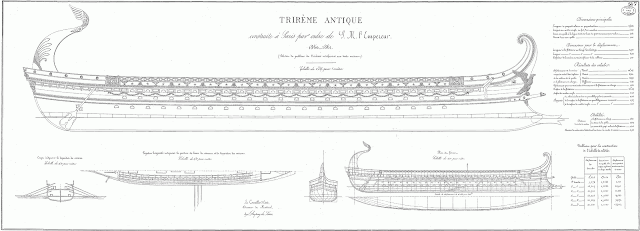
 |
| Trireme oar-powered battleship of the ancient Mediterranean Sea |
statcounter code
Friday, December 28, 2012
Free Ship Plan: Ancient Trireme
While looking through the French Atlas of Marine Engineering I stumbled across this really cool plan for a trireme, the ancient rowed battleships of Greek and Roman empires. This would make a really cool ship model with a tiny bronze ram at the bow and a gazillion oars protruding from the sides.
Monday, December 24, 2012
Free Ship Plan: 77-foot North River Schooner
Another interesting free ship plan from Wooden Ship Building by Charles Desmond is the North River Schooner. The plans are a little rough, as the pages are yellowed and the ink faded, but the missing bulwark lines can be recreated using a coffee stir as a batten. Hold it on edge and bend it to match the existing lines on either side of the missing portion. The wood will give you an accurate curve to trace with a pencil to fill in where the lines are too faint to see.
This 77-footer is typical of the shoal draft centerboard sailboats used on the Hudson River to haul bulk cargo in the 19th Century. When it was extended, the centerboard acted as a keel, giving the boat stability when tacking to windward, keeping it from "crabbing" - moving sideways rather than forward. When retracted, it allowed the boat to get into shallow waters common along the river, or even be beached for unloading where a harbor wharf wasn't available.
From The Sloops of the Hudson, by By William E. Verplanck and Moses W. Collyer (The Knickerbocker Press 1908):
 |
| Sail Plan for a 77 foot North River Schooner |
 |
| Section, Sheer, and Waterline Plans of North River Schooner |
This 77-footer is typical of the shoal draft centerboard sailboats used on the Hudson River to haul bulk cargo in the 19th Century. When it was extended, the centerboard acted as a keel, giving the boat stability when tacking to windward, keeping it from "crabbing" - moving sideways rather than forward. When retracted, it allowed the boat to get into shallow waters common along the river, or even be beached for unloading where a harbor wharf wasn't available.
From The Sloops of the Hudson, by By William E. Verplanck and Moses W. Collyer (The Knickerbocker Press 1908):
The North River schooner was built on somewhat the same plan as the sloop, having a center board, and her bowsprit carried out almost horizontal, and one head-sail, the single jib, attached to a jib-boom, as with the sloop.* (A few of the later schooners carried a flying-jib.---W.E.V.) She carried not foretopmast. The skippers contented themselves with a maintopsail only and set it like the sloop’s. The foresail was of good size compared with the mainsail and not a mere “ribbon” such as the racing schooner yacht now carries. The quarter-deck was replaced in the later schooners by a trunk cabin, lighted from the side and end, affording smaller and less pleasant accommodations than those below the quarter-decks of the old packet sloops with their large windows for light and air at the stern.
The schooners were not as good in windward work as the sloop, but with a fair or beam wind they were faster. The rig, however, soon commended itself for the sloop with her long boom, tall mast, and heavy mainsail was difficult to handle at all times and especially in a blow and required a crew of six men to the schooner’s four. The first of the schooners were converted sloops. From which many of the larger ones were changes to save expense of operation. Late, about 1865 there was built a new type of schooner for the Hudson which though rigged the same was a wider and shallower boat thus giving her greater carrying capacity and permitting all the cargo to be placed on deck for expedition in loading and unloading. She was quite sharp forward, which—with other good points in her model—made her good sailer.
Labels:
19th Century,
boat models,
cargo,
free ship plans,
Hudson River,
maritime history,
model ship building,
New England,
sailing ships,
schooner,
ship,
ship models,
ship plans,
vessels,
wooden
Wednesday, December 12, 2012
Scarf Joints: Essential in Shipbuilding
In building full-size wooden ships, it is impossible to get wood timbers long enough to make some of the structural members. In these cases, several pieces are joined together lengthwise by "scarfing": tapering the ends, lapping them and then fastening the two together.
 |
| Types of Scarphs - illustration from The Construction of a Wooden Ship by Charles G. Davis |
Scarfing timbers together is one of the most important processes in wooden shipbuilding and deserves detailed explanation.
The length of the scarf is shown in the plans or specifications and is usually given to the workmen by the foreman who lays out the work. The foreman also tells the workmen the depth to make the pointed end or nib, as it is called, but if he does not, 23 percent, or about one-fifth the depth of the timber, is a safe rule to cut to.
Care must be taken not to run the saw out any deeper so as to make a weak spot where the timber may split when bent. The scarf is first marked out on the timber and is then sawed out on a band saw or circular saw. If neither is available a 5-foot or 6-foot cross-cut saw may be used and several saw cuts made and the chunks of wood spilt, chopped, or dubbed out with a broadaxe. The timber is then trimmed or dubbed off. carefully to the line on the face or working side of the timber with an adz. The remaining wood is then worked off, using the carpenter's square frequently to see that too much is not cut away. The face of the scarf is finished off with a plane so that the carpenter^s square fits perfectly on its face when applied at various points across it.
There are several kinds of scarfs; the plain scarf, flat scarf, hook scarf, lock scarf, etc. The plain and flat scarf are the ones most commonly used and the hook scarf comes next. The lock scarf has an opening in which is driven an oak wedge or key for the purpose of keying and setting the ends of the scarf tightly together. The keel scarf with tenons is a combination of the plain and hook scarf and is more difficult to cut and fit. To prevent pulling apart short wooden pins, called dowels, fitted vertically in the face of the scarf, were formerly used, but nowadays the more common practice is to bore across at the seam where the two faces meet and drive in treenails, long wooden pins about the size and shape of broom handles and usually made of locust wood. Sometimes a better fit can be obtained by running a cross-cut saw through the joint. When the surfaces fit perfectly with their nibs or ends pushed tightly together by means of a jack at one end, they are either clamped together with big iron screw clamps or are wrapped with chains with wedges driven between the chains and the timber so as to draw the wood tightly together.
Vertical holes are bored and iron or steel clinched fastenings and treenails are driven by the use of compressed air tools — air drills and air hammers. In some yards electric drills are used. Where air or electric tools are not provided the holes are bored with hand augers and the dowels and treenails are driven by sledge hammers.
These strong joints are also useful in model ships, so it is a good idea to learn how to create them in miniature.
Saturday, December 8, 2012
New Illustrations on the Shipbuilding Terms Pages
We've added some great illustrations of blocks and tackle from Wooden Ship Building by Charles Desmond to the Shipbuilding Terms pages:
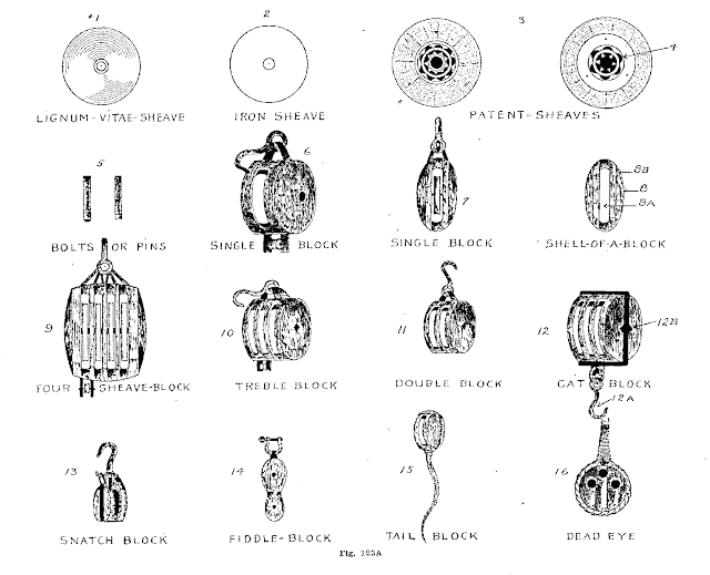 |
| Types of Sheaves and Blocks Illustration from Wooden Ship Building by Charles Desmond |
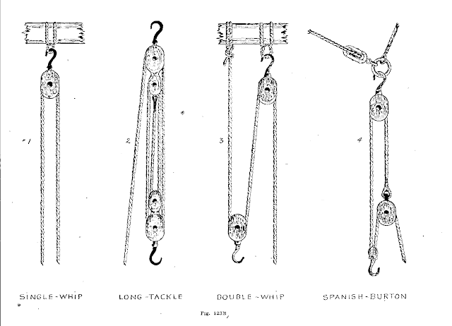 |
| Types of Tackle Illustration from Wooden Ship Building by Charles Desmond |
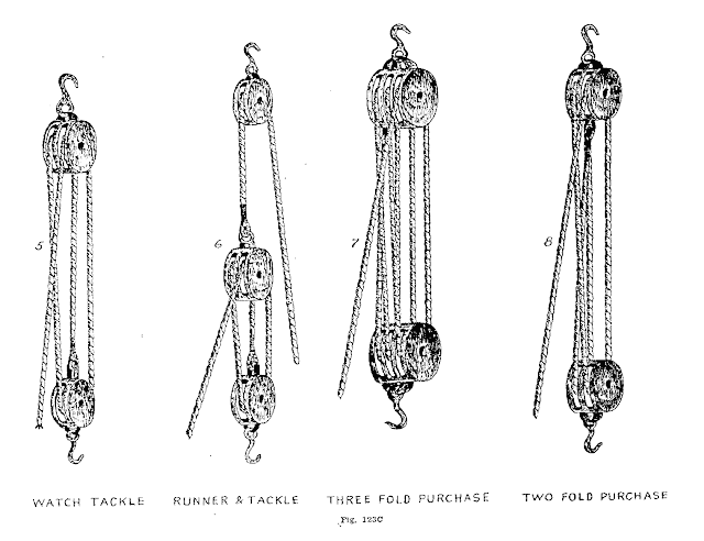 |
| Types of Tackle Illustration from Wooden Ship Building by Charles Desmond |
Wednesday, December 5, 2012
Free Ship Plan 19th Century Steam Fishing Trawler
 |
| Steam-powered 19th Century fishing trawler designed by W.E. Redway |
These plans, from the University of Washington Freshwater and Marine Image Bank, are of a late 19th Century steam-powered auxiliary fishing trawler of about 80 feet in length, designed by W.E. Redway.
 |
| Deck and inboard profile view of 19th Century Great Lakes steam-powered fishing trawler designed by W.E. Redway |
W. E. Redway was a Great Lakes shipbuilder in the late 1800s.
Born in England, his father was also a shipbuilder. Redway served an apprenticeship in the Chatam dock yard in England, followed by positions in various shipyards "on the northeast coast of England and on the (River) Clyde," according to an 1897 profile in The Globe newspaper in Toronto. The River Clyde, flowing through Scotland's industrial city of Glasgow, was a major shipbuilding center during the Industrial Revolution.
Redway moved to Toronto, Canada in 1886.
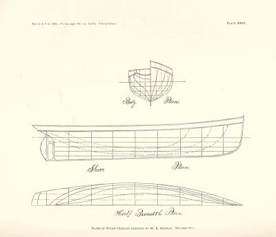 |
| Body, Sheer, and waterline plans of 19th Century Great Lakes steam-powered fishing trawler designed by W.E. Redway |
According to The Globe newspaper profile, Redway "up to June 1897, planned and constructed eleven steam vessels. These were the Imperial, the Mayflower, the Primrose, the Garden City, the Mascotte, the Mistassini, the Medora and others. He also framed the Gooderham yachts Cleopatra and Oriole. Hearing of some of his good work, the managers of the Union shipyards at Buffalo sent for Mr. Redway, and he was there second in charge of the building of the steamer Ramapo, being occupied for six months of the year of 1895 at that work."
Labels:
19th Century,
boat models,
Canada,
fishing,
free ship plans,
Great Lakes,
maritime history,
model ship building,
sailing ships,
ship,
ship models,
ship plans,
steamer,
vessel,
vessels,
wooden
Tuesday, December 4, 2012
Our Favorite Model Shipbuilding Book
One of the best all-around ship model building books for those contemplating building from scratch, Charles G. Davis' The Shipmodel Builder's Assistant also has tons of useful info ship model kit builders can use to improve their result.
Sunday, December 2, 2012
New Illustrations in Shipbuilding Terms pages
We've been adding illustrations from vintage shipbuilding books to our Glossary of Shipbuilding Terms pages. Check them out:
 |
| Types of Rabbets, illustration fromThe Elements of Wood Ship Construction by William H. Curtis |
Subscribe to:
Posts (Atom)
